


The Technology
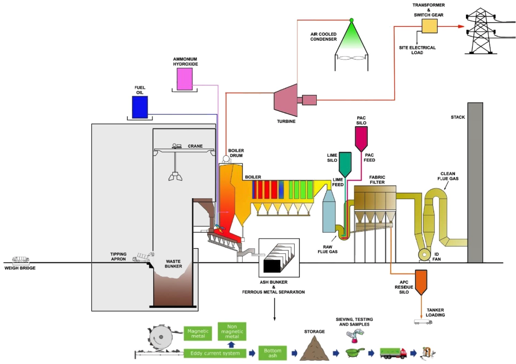
All energy from waste facilities comprise the basic suite of process elements:
Waste reception/handling and storage
Waste combustion and steam raising
Power generation through a steam turbine
Management of solid and gaseous products of combustion

Waste reception/handling and storage
Waste is collected by Gloucestershire’s Waste Collection Authorities (District Councils) and transported to the facility. This waste is delivered into an enclosed reception hall and deposited into a deep bunker capable of storing up to 11 days worth of collected waste. The air that is used to aid combustion is drawn into the facility through the reception hall and bunker so that any odours are contained within the facility. Waste is picked up from the bunker and loaded into the combustion grate feed hopper using overhead cranes, which are managed via the facility control room that overlooks the bunker.

Waste combustion and steam raising
The facility uses an inclined moving grate to transport waste across the burning zone. Before waste can be combusted, the grate chamber has to be heated to a minimum of 850°C using oil burners. Once waste combustion has started it continues unaided and the burners are switched off, only to be reignited if the grate chamber temperature falls below 850°C. Air for the combustion process is pre-heated through a heat exchanger, using steam that has passed through the turbine.
The boiler comprises a water jacket of steel tubes that surrounds the grate and a series of horizontal tubes extending through the boiler hall to maximise the contact area between the hot gases of combustion and the boiler tubes. At its hottest part in the boiler the steam reaches over 425°C at 60 bar pressure.
The facility runs continuously 24/7 with a planned shutdown for around two weeks each year for maintenance.

Power generation though a steam turbine
The high quality steam is fed into a conventional steam turbine, which spins at up to 5,000 rpm. The turbine is connected via a gearbox to the generator, which produces electricity at 11 kV.
After supplying the facility's own needs, the excess electricity will be exported to the national grid - enough to power around 25,000 homes. The electricity is stepped up to 33 kV through a transformer on site, and passes via a substation into the local grid.
Having utilised the energy, the process steam is passed back into water via air-cooled condensers, and is circulated back into the boiler for re-heating. The water/steam cycle is designed to maximise the energy recovery from the combustion process.

Management of gaseous products of combustion
The flue gases created by waste combustion are first quenched in a conditioning tower then scrubbed with a mixture of lime and activated carbon in order to reduce acidity and capture potentially harmful toxins. The gases are then filtered through a series of conventional bag filters to reduce the particulate matter in the flue gas stream. Together, the spent lime compound and particulates are classed as a hazardous waste and must be managed accordingly. Traditionally these products, referred to as Air Pollution Control residues (APCr), are taken in vacuum tankers for disposal at appropriate hazardous waste landfills.
The cleaned flue gases emitted via the stack must fall within strict limits imposed by the Environment Agency through the facility’s Environmental Permit, in accordance with the Industrial Emissions Directive.

Management of incinerator bottom ash
The Incinerator Bottom Ash (IBA) from the combustion grate comprises inert aggregates, ceramics, glass, clinker, and some metals. The IBA is cooled in a quench bath (using collected water from the site), before being processed to recover the metals, and graded as a construction aggregate.
